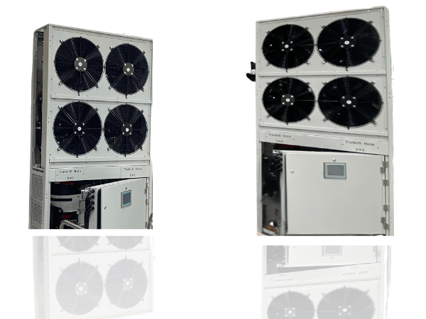
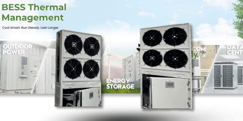
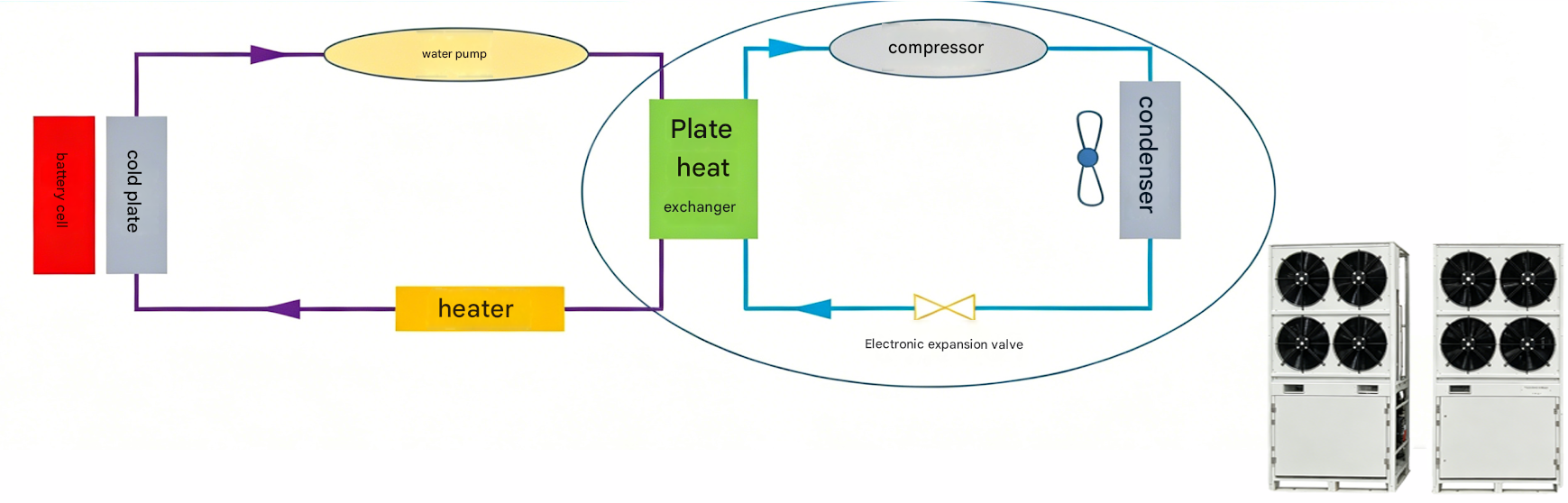
The GUCHEN energy storage liquid cooling unit is specifically designed for energy storage systems, providing precise liquid-based temperature control for batteries. It effectively overcomes the cooling limitations of traditional air-cooled solutions in high-power and high-energy-density applications, enhancing battery system stability and safety while extending overall service life.
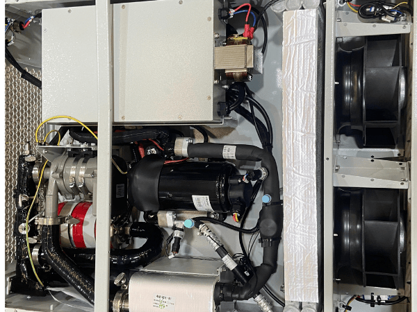
Leveraging extensive technical expertise and industry experience, GUCHEN has established a professional R&D team focused on thermal management for new energy applications. The liquid cooling unit is designed according to the actual operating conditions of energy storage systems, delivering efficient cooling and heating control to ensure stable operation under various conditions.
Compared to air-cooling solutions, liquid cooling offers higher specific heat capacity and superior thermal conductivity, enabling rapid and uniform heat dissipation. This effectively prevents localized overheating and temperature imbalances, improving system reliability and extending service life.
In terms of structural design and manufacturing, GUCHEN’s energy storage thermal management prioritizes safety and stability, ensuring long-term sealing and reliability. It provides a robust thermal management foundation for energy storage systems.
| Parameter | 5 kW Unit | 8 kW Unit | 20 kW Unit | 40 kW Unit | 50 kW Unit | |||
| Cooling Capacity |
5KW |
8KW |
20KW |
40KW |
50KW |
|||
| Operating Voltage |
220V/380V 50/60Hz AC |
|||||||
| Control Voltage | DC 24V | |||||||
| Standard Dimensions (mm) |
900*820*260 |
1150*275*1050 |
1000*630*2400 |
1000*630*2400 |
1000*630*2400 |
|||
| Refrigerant Type |
R134a |
|||||||
| Protection Level |
IP67 |
|||||||
| Outlet Size |
CQC20/25 |
DN40/50 |
||||||
| Communication Interface |
CAN/RS485 |
|||||||
| PTC Heating Capacity |
2.5KW |
2.5KW |
8KW |
16KW |
16KW |
|||
| Water Pump Power |
300W |
300W |
1.5KW |
3KW |
3KW |
|||
| Fan Power |
3*120W |
3*120W |
3*300W |
6*300W |
6*300W |
|||
The coolant absorbs heat from the battery cold plates and releases it through the evaporator. Driven by the water pump, the coolant then circulates back into the cold plates to continuously absorb heat generated by the equipment.
During operation, the evaporator (plate heat exchanger) absorbs heat from the coolant circulation system through refrigerant evaporation. The refrigerant is then compressed by the compressor and enters the condenser, where heat is released into the surrounding air through condensation. Afterward, the condensed refrigerant returns to the evaporator through the expansion valve for another evaporation cycle, repeating the process continuously.
